Updated June 9, 2023

Introduction to UML Activity Diagram
To understand UML Activity Diagrams, we first need to understand what the UML Diagram means. UML stands for Unified Modelling Language. A standardized set or a collection of diagrams helps the software developers and architects understand the software flow. In other words, UML Diagrams are diagrams that depict how the software system is going to function.
UML Diagrams are divided into three types:
- Structure Diagrams
- Interaction Diagrams
- Behavior Diagrams
What is a UML Activity Diagram?
A UML Activity Diagram is a behavioral diagram out of the above-mentioned three types of UML diagrams. Now, how are they different from UML diagrams? So activity depicts what action is going to take place in the process. It is a pictorial representation of how the software system will function. At the time of execution, the software system must function according to the required flow, so activity diagrams depict it as a forward and reverse engineering process/actions.
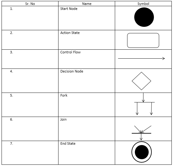
Symbols and Components of UML Activity Diagram
Beforehand, one must know how to draw the UML activity diagrams; you will need the following components and symbols to represent them.
1. Starting state
The activity has not yet utilized or changed the starting state. Activity Diagrams start from this step. Also known as the entry state. Start Node is the starting point of any activity.
It is depicted as:

2. Action State
A step in which the users or software performs a certain task. It represents an action that will take place at this stage of the software system. Generally depicted with the rounded-edged rectangle.
It is depicted as:

3. Control Flow
Connectors between two states or two actions to depict the flow. Shows the sequence of execution. Also known as paths. One action state can have multiple control flows input and also output to another action state. A single-headed arrow represents the control flow.
It is depicted as:
![]()
4. Decision Node
A conditional node or a decisional node is one where there are multiple options available. Or two or more conditions can be considered at the point of the software system.
Example: There’s an ice cream shop. A person enters that shop and wants to buy one of the many options available. Now, if he chooses, Vanilla flavor, server 1 has to give it to him; else he chooses other flavors, then others have to serve it to him. So this is the condition in the activity diagram. It is drawn as a diamond shape with multiple inputs and outputs.
It is depicted as:

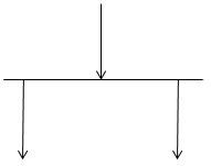
5. Fork
Two processes execute, run, or process either concurrently or in parallel at this location. It generally includes a single input but may or may not get one output.
Example: There’s one ice cream shop. A person tends to buy ice cream for himself and his friend. Now, both of them buy the same vanilla flavor, but one of them wants choco-dip, and the other wants to have fruits to be put upon it. So, here the input is the same, that is, of vanilla ice cream, but the output results are different. So, this is a perfect example of a fork.
It is depicted as:
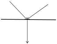
6. Join
A join is one where two results of concurrent activities add and form a single result. When you join, you input multiple things but only receive one output. Two activities yield two results, while one activity yields one result.
Example: There is a requirement for a sandwich. But first, we need to have tomatoes and spinach for it.
It is depicted as:
7. End State
This is the last stage of the UML activity diagram. This is where the activity ends in a software system ends.
It is depicted as:

Advantages and Disadvantages of UML Activity Diagram
Following are some advantages and disadvantages of the UML activity diagram:
Advantages:
- Using diagrams can simplify the explanation of complex stages or steps in a software system.
- Dynamic modeling of a software system.
- Each and every activity flow in the system can be explained as it is.
- Methods, functions, and operations can be explained in detail.
- Depicting business processes and flows can be done quickly.
- Simplified view, though the complex system.
- Business requirement analysis.
- The understanding of system requirements is explained lucidly and simply.
- The workflow provides a detailed explanation of how the system interacts with the user and vice versa.
Disadvantage:
- The only drawback of the UML Activity Diagram is that the messages or communications between two components or the user cannot be shown.
Symbols used in the UML Activity Diagram
Below is a table containing the symbols commonly used in UML activity diagrams:
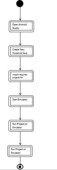
How to make a UML Activity Diagram with an Example
We’ll consider an example of developing software in Android Studio:
- Open Android Studio.
- Create New Project & Save the project under a unique name.
- To incorporate the new packages required for the project, you need to import them.
- Start the emulator.
- Run the project on the emulator.
- Exit Project.
UML Activity Diagram:
Conclusion
So, in all, we can say that UML Activity Diagrams are necessary during and before the development of any software system. It is very useful in documenting and depicting visualizing the exact process and steps involved in the developmental process. It is possible to display all the complex stages rapidly. Knowing the notations correctly can quickly draw the UML activity diagrams. The most important part of using these diagrams is anyone can draw them according to the flow and at almost every step of the software system development life cycle. Many online software helps draw the UML Activity Diagrams like SmartDraw etc.
Recommended Articles
This has been a guide to UML Activity Diagram. Here we discuss the introduction, symbols, components, advantages, and disadvantages of the UML Activity Diagram. You can also go through our other suggested articles to learn more –