List of AutoCAD Commands (Table of Contents)
- Drawing Commands
- Editing Commands
- Text and Annotation Commands
- Object Manipulation Commands
- Miscellaneous Commands
What are AutoCAD Commands?
AutoCAD is a useful software for creating designs, particularly in 2D format. It supports various commands and shortcut keys to execute multiple procedures and draw objects efficiently.
Mastering the following list of AutoCAD commands is key to efficiently creating complex designs. These commands help the user draft, model, and customize the necessary tasks effectively and efficiently.
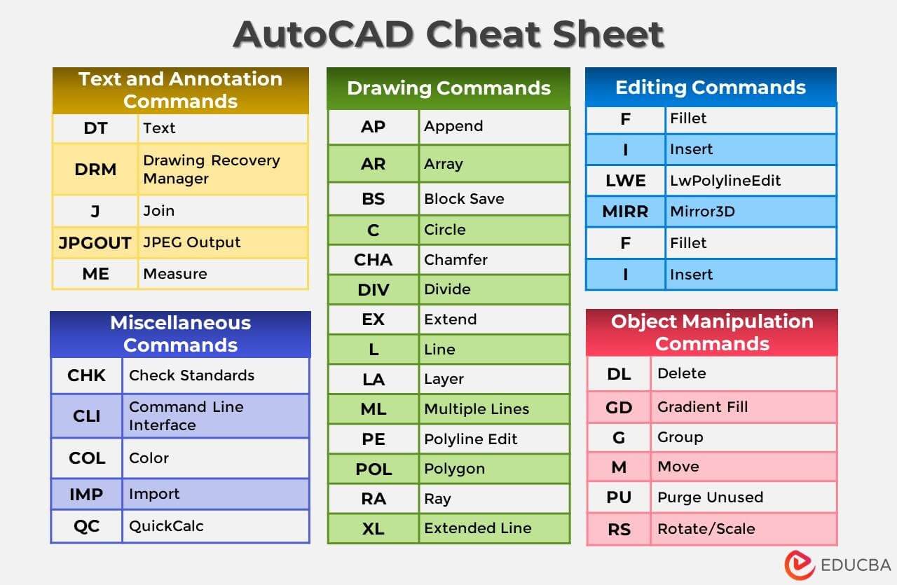
List of Basic AutoCAD Commands
The table below provides a list of AutoCAD commands for this software. The following commands can be executed if the user enters the specific keywords at the command line on the interface or by pressing CTRL+9.
All the following AutoCAD commands and shortcut keys are available in a PDF for easy access anytime.
List of AutoCAD Commands for Drawing
| Command | Full Form | Description |
| AL | Align | Aligns an object with another object by specifying source and destination points. Allows scaling of source objects relative to the destination object. |
| AP | Append | Appends one object to the other by overlapping or combining them. |
| AR | Array | Creates an array of objects based on a desired profile. |
| ARC | Arc | Creates an arc by specifying the starting point/center and two endpoints. |
| BH / H | Hatch | Applies a hatch pattern with a color or gradient effect to a closed area in the drawing. |
| BR | Break | It breaks an object into two parts. |
| BS | Block Save | Saves a particular object as a block for future reference. |
| C | Circle | Inserts a circle by selecting a starting point and entering the radius. |
| CHA | Chamfer | Creates a chamfer, i.e., a symmetrical sloping surface between two non-parallel lines. |
| CO | Copy | Duplicates a specific object to a different location as needed. |
| DI | Distance | Measures the angle and distance between two points in a drawing. |
| DIV | Divide | Divides an object into smaller segments, such as dividing a line into multiple shorter lines. |
| EX | Extend | Extends or stretches an object to meet another object’s size. |
| L | Line | Draws a simple line by defining the starting point and endpoint. Can also define the line using an angle and radius. |
| LA | Layer | Manages layers inside the drawing through a dialogue box. |
| LO | Layout | Creates and modifies different drawing layout tabs. |
| ML | Multiple Lines | Draws multiple parallel lines. |
| MI | Mirror | Creates a mirror image of a particular object. |
| MT | Text | Creates a text object for writing a multi-line paragraph. |
| OF | Offset | Creates a parallel copy of an object at a specific distance. |
| PE | Polyline Edit | Edits a polyline, allowing closure, joining, width adjustment, vertex editing, fitting lines, or converting polylines into splines or de-curve lines. |
| PL | Polyline | Creates a polyline in the drawing, with each endpoint connected to the start of the next line segment. |
| POL | Polygon | Constructs a polygon by specifying the number of edges and the center. It can be inscribed or circumscribed. |
| RA | Ray | Draws a semi-infinite line (ray) from a particular point. |
| REC | Rectangle | Specifies the length and breadth of a rectangular polyline by defining a starting point and a point diagonally opposite. |
| RO | Rotate | Rotates an object to a specific point by selecting the object and a base point for rotation. |
| ROt | Rotate3D | Rotates an object in 3D space by selecting an axis and angle. |
| SC | Scale | Resizes an object using a scale. |
| SL | Slice | Divides a 3D surface using a cutting plane. |
| SM | Move | Moves specific objects to a new desired location. |
| ST | Stretch | Stretches a particular object up to a specific point. |
| TB | Table | Inserts a table with a desired number of rows and columns into the drawing. |
| TR | Trim | Trims an object based on another object. |
| TRi | Trim3D | Trims a 3D surface based on another 2D or 3D object. |
| XL | Extended Line | Creates a line of a specific length. |
List of AutoCAD Commands for Editing
| Command | Full Form | Description |
| E | Erase | Erases the selected object from the AutoCAD window. |
| F | Fillet | Creates a fillet/arc between two intersecting lines. |
| I | Insert | Inserts a block from a specified location into the drawing. |
| LWE | LwPolylineEdit | Edits a lightweight polyline by adding or removing vertex points. |
| MIRR | Mirror3D | Creates a duplicate (mirrored) copy of a particular 3D object. |
| RE | Regen | Regenerates the drawing, taking existing updates into account. |
| REN | Rename | Renames layers and blocks inside the drawing. |
| U | Undo | Undoes the previous commands. |
| UN | Units | Selects the drawing’s measurement units, such as units, inches, millimeters, etc. |
List of AutoCAD Commands for Text and Annotation
| Command | Full Form | Description |
| DT | Text | Creates a text box for entering a single sentence. |
| DRM | Drawing Recovery Manager | Displays previous, ongoing projects unsaved due to system failure, acting as an Auto Drawing Recovery. |
| J | Join | Joins objects together to create a new object by overlapping the existing ones. |
| JPGOUT | JPEG Output | Saves the AutoCAD drawing as a .jpeg file. |
| ME | Measure | Measures the dimensions of an object. |
| SP | Spell Check | Checks the spelling of all words inside the drawing. |
| T | Text | Inserts multi-line text into the drawing. |
List of AutoCAD Commands for Object Manipulation
| Command | Full Form | Description |
| DL | Delete | Deletes a particular object from the drawing. |
| GD | Gradient Fill | Fills a particular area with a gradient effect. |
| G | Group | Groups multiple objects into a single object. |
| M | Move | Moves an object to another position by selecting the object and specifying the new location. |
| PU | Purge Unused | Opens a dialogue box to remove unused or unwanted elements from the drawing. |
| RS | Rotate/Scale | Rotates or Scales an object by specifying the parameters. |
List of AutoCAD Commands for Miscellaneous Purposes
| Command | Full Form | Description |
| CHK | Check Standards | Performs a check for violations of standards in the drawing. |
| CLI | Command Line Interface | Shows the command line in every drawing. |
| COL | Color | Opens a color selection dialog box. |
| IMP | Import | It helps to insert a file of any format into the drawing. |
| QC | QuickCalc | Opens QuickCalc for smooth calculations. |
| QSAVE | Quick Save | Saves the ongoing drawing. |
| Z | Zoom | Enables the user to zoom in or out, increasing or decreasing the screen size. |
AutoCAD Shortcuts
AutoCAD also supports basic shortcut keys, mainly useful in Microsoft Applications. The following are some of the main shortcut keys a user can use to make AutoCAD easier to use.
| Shortcut Key | Purpose |
| CTRL+E | To shift between system displays. |
| CTRL+F | To display snap points with the help of the cursor. |
| CTRL+G | To enable or disable grid display. |
| CTRL+H | To switch between different styles. |
| CRTL+SHIFT+H | To show or hide color palettes. |
| CTRL+I | To shift between the display of the coordinates in the status bar. |
| CTRL+SHIFT+I | To apply geometric restrictions on the objects. |
| CTRL+0 (zero) | Clean the screen by hiding the ribbon, palettes, and toolbar. This is useful to increase the drawing area size. |
| CTRL+1 | To open the Property Palette that displays the properties of a particular object. |
| CTRL+2 | To open the Design Centre Palette. This palette allows the user to manage the drawings internally and externally. |
| CTRL+3 | Open the Tool Palette, which contains various tools, commands, and blocks. |
| CTRL+4 | To open the Sheet Set Palette for managing multiple sheets and layouts. |
| CTRL+6 | To open the DBConnect Manager that connects the user to external databases. |
| CTRL+7 | To open the Markup Set Manager Palette, which helps organize and analyze annotations. |
| CTRL+8 | To open QuickCalc for calculations and conversion of units of measurement. |
| CTRL+9 | To determine the position of the command line that helps the user to enter prompts or commands. |
Advanced AutoCAD Commands
| Command | Description |
| Layer & Drawing Management | |
| LAYISO | Isolates selected layers and hides others for focused editing |
| LAYUNISO | Restores all previously hidden layers |
| PURGE | Removes unused layers, blocks, and styles to reduce file size |
| OVERKILL | Deletes duplicate or overlapping objects in a drawing |
| Precision & Object Control | |
| OSNAP | Enables precise snapping to endpoints, midpoints, centers, etc. |
| POLAR | Guides drawing at predefined angles |
| ORTHO | Restricts cursor movement to horizontal or vertical |
| TRACKING | Uses temporary alignment paths for accurate placement |
| Block & Attribute Commands | |
| BEDIT | Edits blocks without exploding them |
| ATTDEF | Creates attribute definitions for blocks |
| BATTMAN | Manages and edits block attributes |
| WBLOCK | Saves selected objects as a new drawing file |
| Annotation & Dimensioning | |
| DIMSTYLE | Creates and manages dimension styles |
| MLEADER | Inserts multi-leader annotation text |
| TEXTALIGN | Aligns multiple text objects automatically |
| FIELD | Inserts dynamic text that updates automatically |
| 3D Modeling & Visualization | |
| EXTRUDE | Converts 2D objects into 3D solids |
| REVOLVE | Creates 3D solids by revolving profiles |
| UNION | Combines multiple 3D solids into one |
| SUBTRACT | Removes one solid from another |
| INTERSECT | Keeps only the common volume of solids |
| RENDER | Generates realistic visual output of 3D models |
| Productivity & Automation | |
| LISP | Runs AutoLISP programs to automate tasks |
| SCRIPT | Executes a sequence of commands automatically |
| PARAMETERS | Applies parametric constraints for dynamic designs |
| ACTIONRECORDER | Records and replays repetitive tasks |
| File & Collaboration Tools | |
| XREF | Attaches external reference drawings |
| ETRANSMIT | Packages drawings with all dependencies |
| PDFIMPORT | Converts PDF files into editable AutoCAD objects |
Frequently Asked Questions (FAQs)
Q1. How do you hide a layer in AutoCAD?
Answer: To hide a layer in AutoCAD, follow the steps below:
Step 1: Open the Layer Properties Manager (type “LA” and press Enter).
Step 2: Locate the layer you want to hide.
Step 3: Click the “VP Freeze” column to toggle the layer’s checkmark.
Step 4: Click “OK”.
Q2. What is the color coding in AutoCAD?
Answer: In AutoCAD, color coding gives specific numbers to colors (1 to 255). It helps distinguish objects by assigning different colors to them for easier visual identification. Colors 1-7 are predefined (red, yellow, green, cyan, blue, magenta, and white), while colors 8-255 can be customized.
Q3. What are the most important AutoCAD commands beginners should learn first?
Answer: Beginners should start with essential commands like LINE, CIRCLE, TRIM, OFFSET, MOVE, COPY, and LAYER, as these form the foundation of most 2D drafting tasks.
Q4. How can I customize AutoCAD commands and shortcuts?
Answer: You can customize commands using the CUI (Customize User Interface) editor, where you can create custom shortcuts, modify existing ones, and assign commands to toolbars or keyboard keys.
Q5. How do I recover lost or unsaved drawings using AutoCAD commands?
Answer: You can use the DRAWINGRECOVERY or RECOVER command to locate and restore unsaved or corrupted drawing files after a system crash.
Q6. How do AutoCAD commands help reduce file size?
Answer: Commands like PURGE, OVERKILL, and AUDIT remove unused or duplicate elements, helping optimize drawing performance and reduce file size.
Q7. Can AutoCAD commands be used for automation and batch processing?
Answer: Yes, AutoCAD supports SCRIPT files, Action Recorder, and AutoLISP, enabling users to automate repetitive tasks and process multiple drawings simultaneously.
Q8. What is the best way to memorize AutoCAD commands quickly?
Answer: The best way is regular practice, using cheat sheets, customizing shortcuts, and focusing on use-case-based learning rather than memorizing all commands at once.
Recommended Articles
This is a guide to the List of AutoCAD Commands. Here we discuss the list of AutoCAD Commands in this software to draw your design. You may also look at the following article to learn more –