UML Class Diagram
Before understanding (Unified Modelling Language)UML Class Diagram we must understand Object-Oriented Design and Analysis. Object Orientation mainly deals with the investigation of the real-time entities which are objects and their relationships. Efficient analysis of the objects starts with identification, followed by functionalities, followed by relationships, and finally, the design is produced.
The above process of Object-Oriented analysis can be described in detail as follows –
- Object Identification – The purpose is to describe the object in a proper way. Then the objects should be identified with responsibilities. Responsibilities are the functions that the objects perform.
- Object-Oriented Design – This is the phase of collaborating the requirements with responsibilities and coming up with the working design of the software system.
- Object-Oriented Implementation – This is the programming phase of implementing the software design using C++, Java, etc. kind of Object-Oriented Programming Language.
A picture is worth a thousand words and a UML (Unified Modelling Language) reflects the meaning of the statement at its best by modeling a software system.
What is UML Class Diagram?
UML Class Diagrams or Unified Modelling Language Diagrams are general-purpose modeling language that is used to visualize a system; especially an object-oriented system. It is an industry-wide accepted standard language for visualizing, specifying, documenting, and constructing artifacts of software systems. UML was pioneered by Object Management Group (OMG) and UML’s first version v1.0 specification was released in January 1997.
UMLs are the union of all modeling languages like use case diagrams, class diagrams, object diagrams, sequence diagrams, collaboration diagrams, state-chart diagrams, activity diagrams, component diagrams, deployment diagrams, and the list goes on. It is the really very big & nice standard that the industry has adopted and embraced.
Distinguishing features of UML –
- It is not a programming language. It is a modeling language. It is different from that of other programming languages like C, C++, Java, COBOL, etc.
- Unified Modelling Language is a pictorial language used to represent the blueprint of software products.
- Even though Unified Modelling Language (UML) was developed to represent the software systems, it can be well extended beyond this boundary to model non-software systems as well. To state an example – a UML diagram to show the flow of the process in a manufacturing unit in a factory, etc.
- UML diagrams are, not code or programs as such. But there are quite a number of tools that use these UML diagrams as inputs to generate code or programs.
- UML diagrams are closely associated with object-oriented analysis and design.
Role of UML in Object-Oriented Design
Object-Oriented Design came into the picture in order to build software products to deal with real-time objects and in order to have a nice overview about this OOP design, in order to have a better logical view of the same, we transform the OOP design into Unified Modelling Languages which are diagrams that represent the whole software system. This is why it is very important to learn OOP concepts before dealing with the UMLs.
Building blocks of Unified Modelling Language and Types of Class Diagrams
As we know that UML models real-time systems, it is important to make a conceptual model using building blocks of UML which are –
- Things
- Relationships
- Diagrams
Things –
Things are the atomic units of Unified Modelling Language (UML) and they can be sub-divided as –
- Structural – These are a static part of the model. They are the units that represent the physical and conceptual elements like a class, interface, use-case, component, or node.
- Behavioral – These are the things in UML that define some sort of interactions, exchange of messages, or direction of the flow.
- Grouping – This is a way of grouping elements of the UML model together. Like a package or a module or a library.
- Annotation – Annotation things are the ones that are informative in nature like captions, remarks, descriptions or comments for the other UML things or components.
Relationships-
Relationships in Unified Modelling Language represent the dependency or the functionality or the association between two UML things. There are four kinds of relationships in UML, as follows –
- Dependency
This is a correlation between two UML things where if one changes then the other changes.
- Association
This represents the involvement of different components in a particular functionality and connects the elements of the UML. There are types of associations –- Aggregation – this is a ‘is part of’ kind of relationship between two components of Unified Modelling Language. In UML way, it is represented using a clear diamond shape.
- Composition – this is a ‘is entirely made of’ relationship between two components of Unified Modeling Language. This is a stronger version of aggregation and parts live or die as a whole. Any change in one component will directly affect the other. By UML standards, it is represented by a black diamond shape (or a diamond shape that is shaded).
- Generalization
This is up to the hierarchy in which a relationship is defined as a UML element to belong to a group that is more generic to define. This is basically the inheritance concept. - Realization
This is a relationship between two UML elements wherein one element defines a task and the other element implements it (or realizes it, to say in other words). This is something that mimics the interface concept of Object-Oriented Programming.
Diagrams –
Combining all the above components to give a meaningful, logical view of the whole software system is what we call as Diagrams. These diagrams will have different shapes for which we can define our own meanings. For example, we can define a square to represent static data and a parallelogram to define a loop.
More on the Class Diagram
The main components of the UML Class diagrams. Class diagrams can be used to represent relationships, classes, interfaces, inheritance, collaboration, and association. Briefly, a class diagram describes different types of objects and static relationships among them.
Let’s try to draw a class diagram of a Student and see how it goes.
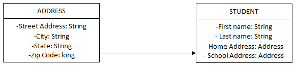
From the above diagrams, you can see that there is a class called Student with different attributes like first name, last name, home address, school address, and for the address which is of same generic structure, it inherits from another class called Address which defines the data structure for address. So, one can understand the relationship (a dependency) between the two. If there were any methods in the class to implement any functionality then they also would be included in the same class diagram rectangles with details about the parameters and return values.
Working with UML Class Diagram
How do we design classes?
- The foremost step is to identify the classes from the project specifications or requirements. Nouns are potential classes, objects, fields. Verbs are potential methods or responsibilities of a class.
- Then you draw all the components using shapes like rectangles, diamonds, ovals, etc.
- Followed by resolving the dependencies or relationships between the components.
Advantages of UML Class Diagram
- UML helps to discover related data and attributes.
- It also helps us understand the relationships between the components (the entities) in a system and also we can optimize it if the relationship is founded to be too clumsy or dependent.
- UML simplifies the design of complex software and also helps in the implementation of OOPs.
- It significantly reduces the burden of explanation by representing the entire system in a few graphical and pictorial diagrams that might have been otherwise difficult to comprehend.
- It gives a logical view of the whole system that is being built.
Disadvantages of UML Class Diagram
- Unified Modelling Language is not preferred for algorithmic computation as it is not data-driven. It is mostly focused only on modeling or design.
- It can give a generic class and flow representation but UML will fail to find the object by object flow of steps in a given problem.
Unified Modelling Language in Artificial Intelligence
Problems in the domain of artificial intelligence are usually complex. One needs a large amount of knowledge and techniques to manipulate that knowledge to create solutions to problems. Though there are a variety of new ways of representing knowledge (facts) exist, Unified Modelling Language remains a good standard again.
In AI terms, there are two types of UML entities.
- Facts – Truths in the real world. Just like objects/classes in Object-Oriented Design.
- Representations – Representation of facts in some formalism. This is where we manipulate the facts.
One way of structuring these entities is at the knowledge level, at which facts are described as informal, colloquial language. Ex-Tiger is the name of a dog. Another way is at the symbol level, at which representations of facts at the knowledge level are defined in terms of symbols that can be transformed, processed, or manipulated by programs.
How this will help you in your Career
A question arises, is UML which is significantly old still relevant for us from the career point of view. The answer is ‘yes’. UML is very useful in any kind of project and especially big projects. Sequence diagrams help two modules understand their flow, use case diagrams help to show the usefulness and functionality of the product, a component diagram shows the product architecture. Basically, UML shows us the big picture of the software system that is being built.
In a sense, UMLs are greatly used by high-level software architects and lead engineers to brief the developers about what needs to be developed. And a section in this article also described its use in the field of Artificial Intelligence. So, yes, having knowledge about UML is of great use in your career.
What is the best way to learn UML?
Well, follow the below steps –
- Don’t refer to the OMG specification at first. Refer to it at a later point in time!
- Learn the basics of UML from online sources like educba, etc.
- Learn the notations to draw and label the Unified Modeling Language diagrams.
- Practice the same with multiple examples!
- Finally, try to use some tools to convert the Unified Modelling Language to actual code.
Tools for creating Unified Modelling Language
There are a lot of tools available to draw a Unified Modelling Language. A few are as follows –
- Violet – It is free and can be found at – https://horstmann.com/violet/
- Visual Paradigm UML Suite – It is paid. It has a few days of trial and it can be found at https://www.visual-paradigm.com/
- Rational Rose – This can be found at https://www.ibm.com/in-en
Conclusion
In conclusion, one can say that UML (Unified Modelling Language) can be defined as a modeling language to model all possible complex software systems and complex practical systems.
Recommended Articles
This has been a guide to the UML Class Diagram. Here we discussed the advantage and disadvantages, the working type of class diagram, role, and features of the UML Class Diagram. You can also go through our other suggested articles to learn more –