Updated March 17, 2023

Introduction to UML Deployment Diagram
UML Deployment diagram is one of the types of UML diagram which is used to define the hardware requirements for the particular product to execute the software; basically, it maps the software design requirement to the physical system which executes the software design and visualize how software interacts with hardware to complete the test execution. To design the deployment diagram, node, component, artifact, and interface notation are used.
Purpose of Deployment Diagrams
Now let us discuss the purpose of deployment diagrams.
The term deployment in the deployment diagram itself specifies the role of this diagram. It is used for describing hardware components where the software components are actually deployed. UML is generally used to describe the software artifacts of a system. However, UML deployment diagrams are a special case of UML diagrams where the main emphasis is on the system’s hardware topology ( here, topology means layout ).
The Main Purpose of the Deployment Diagram
- To represent the hardware topology of a system.
- Represent how different hardware components are inter-connected and how these hardware components are used to deploy software components.
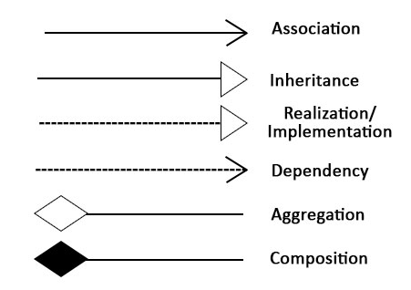
Symbols and Components
Let us first understand two basic terms that we will frequently use (Symbols and Components).
Symbols
UML deployment diagram symbols represent a node, object, node instance, component instance ( here component instance means a replica or copy of component ), interface, etc. These symbols help us to create an accurate diagram for documentation.
A similar image which could be referred to
Components
Components represent different hardware nodes in which software resides.
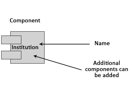
Note that it is symbols that connect different components and help us make a good UML deployment diagram.
How to Draw a Deployment Diagram?
This is one of the most important sections of this article, as we are going to discuss how we can draw a deployment diagram. The most important component of a deployment diagram is nodes. Nodes are simply the physical hardware that is used to deploy the application. Therefore, an efficient and good deployment diagram is very important as it covers the following important aspects. These important aspects are as follows:
- Maintainability: The system designed should be easily maintainable.
- Portability: The system should be designed in such a way that it is easy to implement new changes.
- Performance: The system should have high performance.
- Scalability: The system should be flexible enough so that it could be easily expanded.
Before making a deployment diagram, two important artifacts must be identified and should be understood properly, and these two important artifacts are nodes and how these nodes are interconnected.
Let us understand this with a simple example.
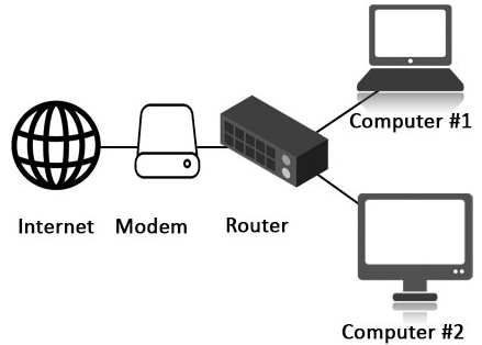
Example
Let us prepare a simple deployment diagram that consists of the following components.
- Server.
- Modem.
- Router.
- User nodes like mobile, printer, etc.
This example is assumed to be a web-based simple application hosted in a clustered environment using participated servers. A user node like mobile will connect our application using the internet through modem and routers.
A simple deployment diagram considering all the above-mentioned points for all this will be.
Now, we can assume that we can make a simple deployment diagram. Let’s do a discussion on our next topic, which is where can we use deployment diagrams.
Where to Use UML Deployment Diagrams?
System engineers mainly consume deployment diagrams. These diagrams help us to describe the physical components like hardware involved, participant nodes, their distribution and how they are inter-connected Deployment diagrams could be assumed as the hardware components where the software components reside.
Deployment Diagrams can be used for the following cases:
- To visualize the hardware topology of a system.
- To represent the hardware details of a system.
- To represent the hardware details of a distributed application.
- & many more…
Conclusion
UML deployment diagram is very important as it helps us visualize and helps us better understand the whole system. A simple and efficient UML deployment diagram greatly helps us make a visual diagram of how these hardware components are inter-linked, the relation between each hardware component, and how the software resides in these hardware components. Also, there are other types of UML diagrams that are important to understand for the efficient making of the systems.
Recommended Articles
This is a guide to UML Deployment Diagram. Here we discuss the purpose of the deployment diagram, how to draw a deployment diagram, where to use UML, symbols, and components with diagrams. You can also go through our other related articles to learn more-