Updated June 7, 2023
UML Use Case Diagram
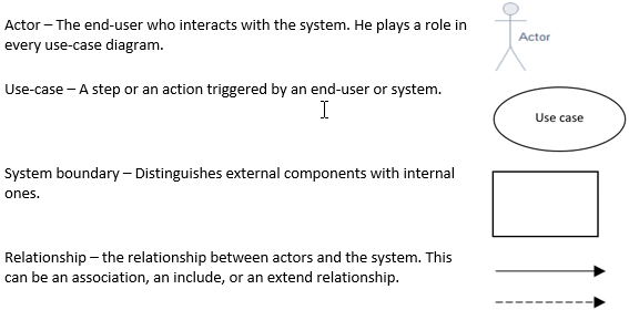
UML use case diagram is one of the types of UML diagram used to represent the dynamic diagram by mapping the structure of the systems using actors and use cases. Use cases represent the set of activities and services the system needs to perform, and actors are the entity that works under defined roles within the system. A use case diagram helps represent the functional requirements of the system using various notations like system, use case, actors, and relationships.
What is UML Use Case Diagram?
It sounds like quite a heavily worded title, doesn’t it? Well, let’s break it down to each word.
1. UML
Unified Modelling Language is a modern approach to the conventional process of modeling and documenting software. This approach is a diagrammatic representation of the components and processes involved in software. It is like explaining the whole software through visual representations so that it is easy to understand and weed out possible flaws and errors in the system. The whole process falls under the larger umbrella of business process modeling techniques.
2. UML Diagrams
Picture those real-life scaled models of various vast architectures, such as a mall or a housing society spread across acres, placed inside nice shiny glass boxes at the reception of the structure. Isn’t it easy to understand the complete structure when modeled as a whole before your eyes?
UML Diagrams are software that those scaled models are to the actual structure. A complete representation of the whole system or a part of it, with the help of diagrams. There are various diagrams serving various purposes. Some examples are:
- Class diagram: Focuses more on the blueprint.
- Sequence diagram: Focuses more on the process from a system perspective.
- Activity diagram: Focuses on the actions from a user perspective.
- Use case diagram: Focuses on the business requirements and many more.
UML Use Case Diagram
The center topic of today’s discussion is the Use Case diagrams. A Use Case diagram models the system’s dynamic behavior when operating. It highlights the high-level requirements of the system. It is modeled to represent the outside view of the system. The use-case diagram explains the various use cases where an end-user can interact with the system. The perspective in the picture is of the end-user.
A simple example of a use-case diagram is how an end-user interacts with the airline ticket booking system.
Some of the use cases in this example could be, but are not limited to:
- A person logs in to search for flights.
- A person books a flight.
- The person reviews his previous flight bookings.
- A person web-checks his flight.
- A person cancels his flight.
As said earlier, a use case diagram models the system’s dynamic behavior. Notice the word dynamic. This implies that some internal or external factors must influence the system’s behavior during run time and make it dynamic in nature. These internal or external agents are known as Actors. A Use-case diagram models the actors, the system, and their interaction. A single use-case diagram can model a particular functionality of the system.
Why Use Case Diagram?
Let’s analyze some Questions and Answers.
1. Why use-case when the activity diagram also models the actions of the system based on the inputs?
Answer:
Yes, but the use case diagram does it from the end-users perspective, whereas the activity diagram does it from the system perspective. An end-user may not know his role through an activity diagram.
2. Well then, sequence diagrams involve actors and the actions they perform at various stages. Why use-case?
Answer:
Sequence diagrams are more detailed versions of user-system interaction. They also involve the internal functioning of the system, interaction between sub-modules, and the time elapsed during internal functioning. An end-user may not be interested in such details. He is concerned with the overall output of the system.
3. I know collaboration/communication diagrams are a simpler version of sequence diagrams. Why can’t I use them?
Answer:
Collaboration diagrams are more straightforward, yet they focus mainly on the communication between the components. This still focuses more on the messages exchanged between the system and sub-modules. An end-user may still find it a little too detailed for his purpose.
4. There is a state-chart diagram as well. They are simple, don’t involve internal sub-modules, and depict end-user interactions. How does the use-case diagram beat it?
Answer:
The primary purpose of state-chart diagrams is to analyze the system’s state at every possible point. They are more suitable for debugging and reverse-engineering the system. Use case diagrams to skip the intermediate states of the system, as the end-user may not be interested in knowing all the states the machine goes through. Moreover, state-chart diagrams don’t focus on the overall requirement as use-case diagrams do. They focus more on a specific input and the concerned output.
So, the takeaway from this discussion is that while many UML diagrams perform similar functionalities, they have a prominent role in understanding the system. A Use-case diagram is as important as any other diagram for documenting the system components of Use case diagrams.
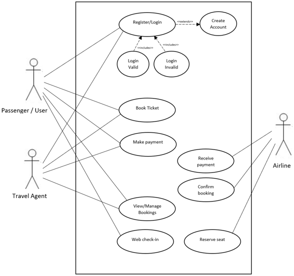
Example of use-case Diagram
Below is a simple example of a use-case diagram for the Airline Ticket booking system. This diagram can be more comprehensive by introducing other actors, such as booking operators, banks, etc. It has been simplified to demonstrate how a use-case diagram is made.
Conclusion
Use case diagrams are simple yet effective for understanding the system from the outside. They are accommodating for the business to define high-level requirements and analyze flaws in the requirements. Understanding use-case diagrams help the business as well as the technical team to get on the same page in terms of requirements.
Recommended Articles
This has been a guide to UML Use Case Diagram. Here we discussed the UML Case Diagram, why it is used, and the components of this diagram. You can also go through our other suggested articles to learn more –