Updated March 16, 2023
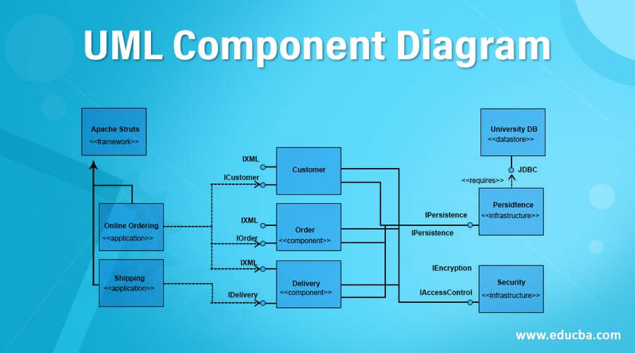
Introduction to UML Component Diagram
The following article provides an outline for UML Component Diagram. Unified Modeling Language that is, UML, is, in simple words, a general-purpose modeling language. The main objective of UML is to visualize the way a system is designed in a standard way. It is also very much the same as blueprints that are being used in other fields of engineering as well. It is not a programming language, but rather it is a visual language.
UML Component diagrams are used to only demonstrate the behavior as well as the structure of a system. UML helps system architects, businessmen, and also software engineers in modeling, design as well as analysis. The OMG, that is, Object Management Group, adopted UML as the standard back in 1997. Since then, it has been managed by them. After that, in 2005, ISO published UML as an approved standard. UML has been revised and reviewed around the years periodically.
What is Component Diagram in UML?
- UML Component diagrams are basically used in modeling the aspects that are physical of object-oriented systems used in visualizing and documenting systems that are component-bases, and it is also used for the construction of executable systems with the help of forward and reverse engineering. Component diagrams are basically diagrams of the class focusing on components of a system that are often used to model the system’s static implementation view.
- It also breaks down the actual system that is under development into various levels of functionality, basically high level. Each component in UML is responsible for only a single clear aim in the entire system, and it interacts with only other essential elements, and that too just on a need-to-know basis.
- The sole and important purpose of a component diagram in UML is to demonstrate the relationship between various components in the system. If we talk about UML 2.0, the word “component” is defined as a module of classes that represents systems or subsystems that are independent having the ability to interface with the rest of the system.
- There is an approach called component-based development, also called CBD, which revolves around all the components. In this approach, the whole system does what it is actually supposed to do since it permits the planner to identify different components. Commonly speaking, if we talk about Object Oriented programming approach, the component diagram always permits a senior developer to group the classes together depending upon their common purpose, thus enabling the developer as well as others to look at the software development project at a higher level.
- Although component diagrams in UML might appear to be complicated at first sight, they are quite invaluable when building our system.
Component diagrams have many advantages that can help your team in various ways:
- It pays attention to how the system’s components relate.
- It emphasizes the behavior of service when it relates to the interface.
- It also imagines the physical structure of the system.
Symbols of UML Component Diagram
UML component diagram symbols are many like component, package, package container, dependency, generalization, constraint, opaque stereotype, note, and many others. Let us go through a few important ones. The symbols are provided next to them.
1. Component
Component in UML is defined as a modular part of a system. It always defines its behavior which is in terms of required and given interfaces.

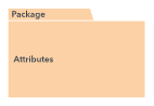
2. Package
Package in UML can be defined as something that can group elements and then gives a namespace for all of those grouped elements.
3. Package containers
Package containers in UML can be defined as something that describes UML elements like classes, components, and use cases.
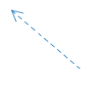
4. Dependency
Dependency relationship in UML can be defined as a relationship wherein one of the elements which are the client uses or depends on another element which is the supplier.
![]()
5. Generalization
Generalization in UML can be defined as the relationship wherein one of the model element, i.e., the child, is based on another model element, i.e., the parent.
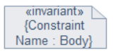
6. Constraint
Constraint in UML can be defined as something that enables us to refine the semantics of the UML model element. It is an extension mechanism. Note in UML consists of either comments or textual information.
Note in UML can be defined as something representing either hardware or software objects that are of a higher level if we compare them to components. components.

7. Interface
In UML can be defined as something that demonstrates the materials that a component will either receive or provide. We can represent interfaces with either textual notes or symbols like the lollipop, socket, or ball and socket shapes.
8. Port
Symbol in UML can be defined as something that mentions a different interaction point between the environment and the component. Ports can be symbolized with the help of a small square.
How to make a Component Diagram?
We can easily make a perfect component diagram in UML from scratch with the help of the Lucid Chart.
All we need to do is follow these steps:
- Either open a blank document or start with a template.
- UML shape library is to be enabled. Then click on “Shapes” o the left side of the editor and check on “UML” in the Shape Library Manager, and then click “Save.”
- Select the shape that you want from the library to be added, and all you have to do is drag that shape from the toolbox into the canvas.
- Draw lines between shapes for modeling the flow, and we are done.
One of the example is as below for Library Management System shown below:
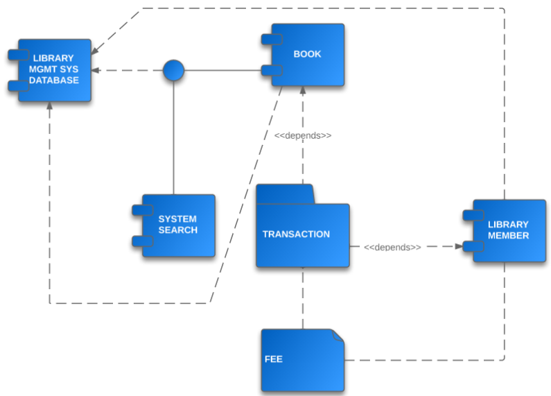
The transactions shown here create a network of relationships between components of the library system. In order to understand how are these relationships working and how the system is functioning overall, you need to examine the UML diagram demonstrated above. You can also use it as a template.
Conclusion
Thus, we can conclude that the component diagram is a really important diagram in which architects will often create quite early in a project. But, its usefulness spans the life of the system. Component diagrams are quite invaluable since they model as well as document a system’s architecture.
Recommended Articles
This has been a guide to UML Component Diagram. Here we discuss the basic concept with different types of symbols explained in detail. You can also go through our other suggested articles to learn more –