Updated September 12, 2023

Introduction to Leader in AutoCAD
The following article provides an outline for Leader in AutoCAD. AutoCAD is 2d and 3d computer-aided designing software developed by Autodesk as its computer-aided engineering designing software. This software has different commands and features to simplify our work. This article will discuss the leader’s command of one of the 2d commands. You can understand a leader as a command by indicating a particular object with its name and dimensions or any other mark using arrows and lines of leader command. Here in this article, we will discuss this command’s important features and analyze its important parameters for our better understanding of leader command. So let us start our discussion about this topic.
How to Use Leader Command in AutoCAD?
We can use this command in auto cad in a few simple steps and get benefit from it in our drawing work, but before starting our learning, let us have a look at the working screen of this software so that there will be no problem occur during our learning about this topic throughout this article.
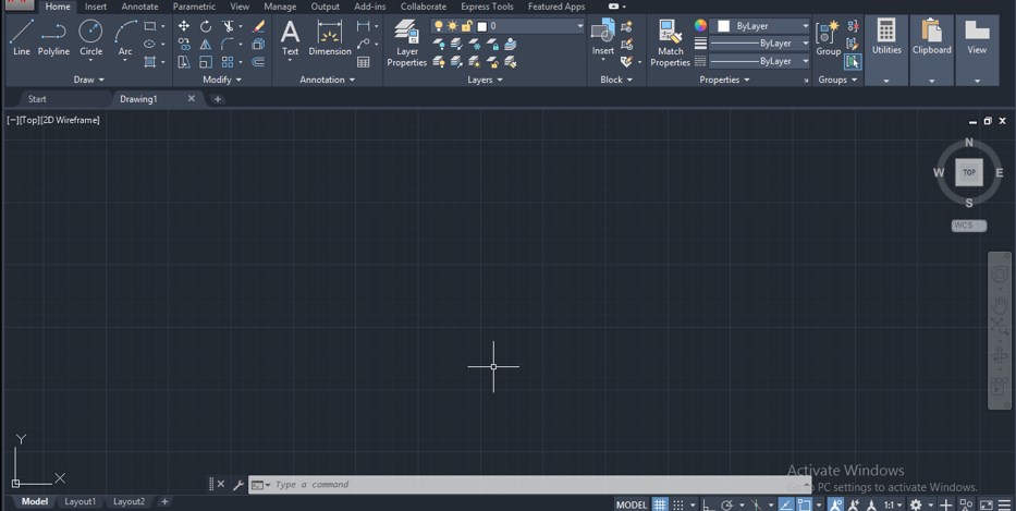
Step 1: At the top of the working screen, there is a ribbon that has several tabs for handling different commands of this software, such as the Home tab, Annotate tab, View tab, Insert tab, and some other important tabs are there, below this, we have a working window in which we can see our current drawing work, this working window also has a navigation cube for changing view of our drawing such as you can change your view in front view, top view, right view or in some isometric views, below this working window we have some navigation tab with workspace switcher option which helps us in our drawing work.
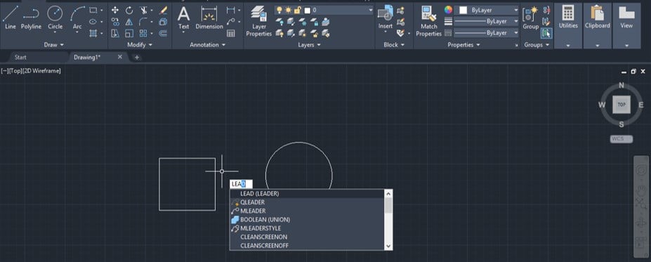
Step 2: Now let us make 2d shapes by using the rectangle and circle commands of the Draw menu of the Home tab of this software for using the leader command on them. I will show you the leader command on the circle. You can apply it on the rectangle and also for indicating its specification. Now press the LEA buttons from the keyboard, then press the enter button of the keyboard for the leader command of this software.
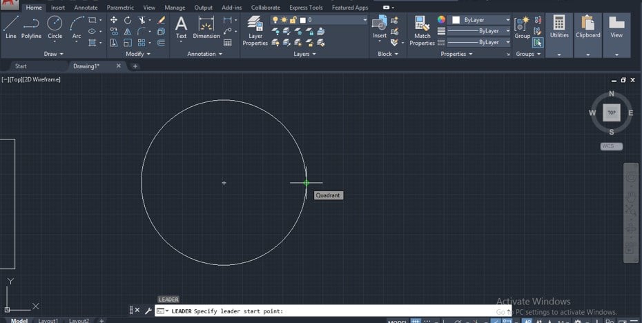
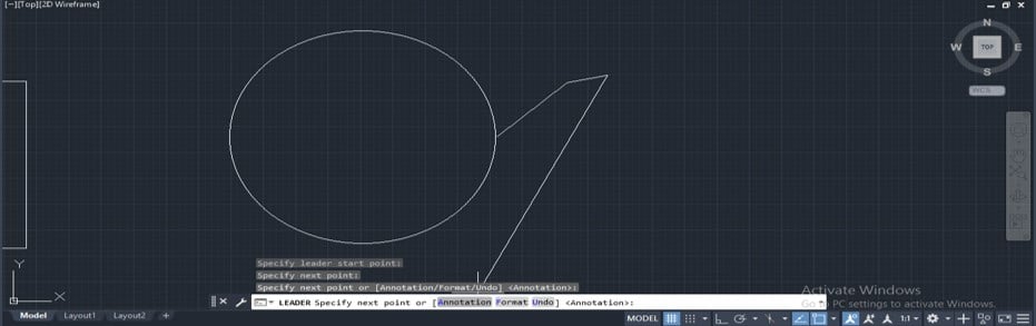
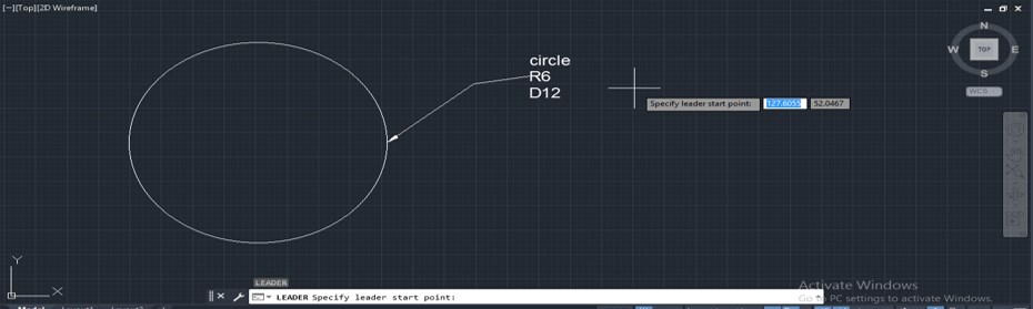
Step 3: Once you enter, the leader command will be active. Now it will ask you to give the first point, which means give the point of that shape you want to indicate with this leader command. I will click on the quadrant point of this circle. You can click anywhere inside this circle or at the circumference of this circle to indicate any specific data of them.
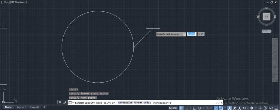
Step 4: Now, it will ask you to specify the second point of leader, which means choosing where you want to type your specification about your selected object or selected point of an object. You can make click again and again for the bending line of a leader according to your requirement.
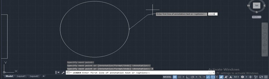
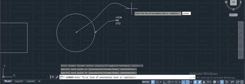
Step 5: Now, when you specify a point where you want to write a specification of a selected object, go to the parameters box of this command, which is at the bottom of the working screen and click on the annotation option of this command for writing some specification of the selected object or you can use shortcut key for annotation option of this command. For the annotation option, press the A button on the keyboard, then presses the enter button on the keyboard for the next step of this option.
Step 6: Type your desired text or data for your selected object. For example, I will type Circle to name it and make enter from the keyboard for the next step.
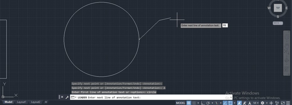
Step 7: Then it will again ask you what you want to type in the next line, so I will give the circle’s radius in the next line by typing R6 as the radius value and then pressing the enter button on the keyboard. You can type any other specification of your selected object in this step. You can type text repeatedly in a new line by pressing the enter button on the keyboard after typing your desired text.
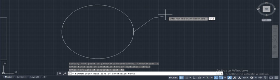
Step 8: Now I will give the diameter of this circle in the next line by typing D12 as the diameter value, then press enter button on the keyboard.
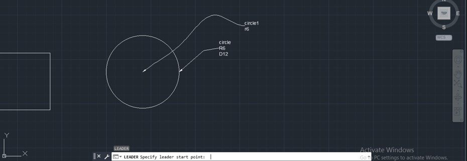
Step 9: Once you have typed all required specifications of your selected object according to your drawing requirement, press enter key two times, and it will mention your given data as a leader like this.
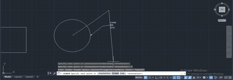
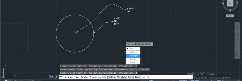
Step 10: Now, let us understand the next option of this command. Again take leader by pressing the shortcut key of this command, then give the first point by clicking at your desired point and going to the parameter box of this command, then click on the Format option of this command, or you can use the shortcut key for the format option press F button of the keyboard then press enter button of the keyboard for seeing next steps of this option.
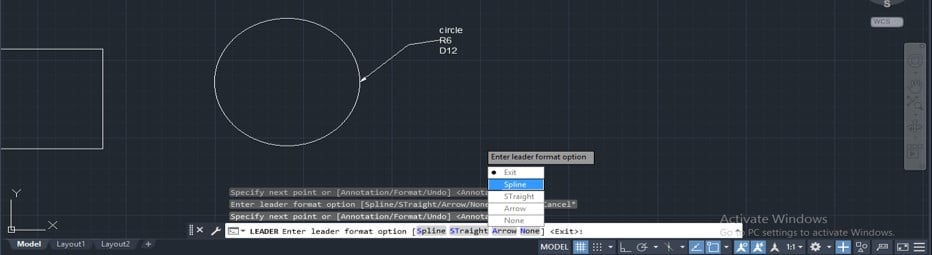
Step 11: Once you click on the Format option, different sub-option of the format will open in a list like this. Now click on the Spline option of this list by clicking on it.
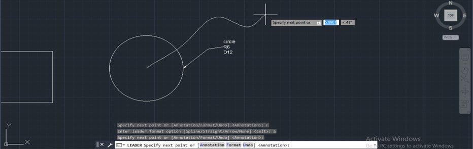
Step 12: Now, the straight line of the leader will convert into spline format, and you can use it as a leader line for specifying any object in your drawing. Now it will ask you to specify the next point, so choose your desired point by clicking on a point in your drawing area.
Step 13: Now click on the annotation to type data or text and type your desired text in the number of the line according to your requirement.
Step 14: Then double enter for applying your given data as we did in previous steps of leader command.
Step 15: You can choose other sub-options of this Format option of leader command and make different types of leaders.
In this way, you can use the leader command in auto cad to specify different objects with different specifications in your drawing.
Conclusion – Leader in AutoCAD
After this article, you can understand what leader command is in auto cad, and you can handle its important features and parameters for getting the best result from it in your drawing work. You can increase your drawing skill by practicing this type of command of this software which must be helpful in your drawing work.
Recommended Articles
We hope that this EDUCBA information on “Leader in AutoCAD” was beneficial to you. You can view EDUCBA’s recommended articles for more information.