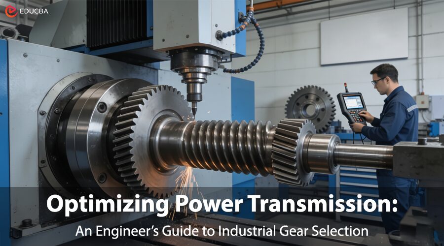
Figure 1: Advanced 5-axis CNC machining enables precise manufacturing of helical gears with tolerances within ±0.005mm, ensuring optimal power transmission in demanding industrial applications.
Introduction to Industrial Gear Selection
Unplanned downtime in gear transmission systems can cause major production losses and serious safety risks in heavy machinery, automation, and renewable energy applications. Premature wear, excessive noise, or low gear efficiency are common headaches many designers face. In most cases, this is not an issue of gear quality but rather poor industrial gear selection, a mismatch between gear type, application scenario, and load characteristics during the design phase.
Traditional gear selection methods often rely on generic handbooks and fail to account for extreme operating conditions. This guide presents an engineering-driven framework for industrial gear selection, grounded in load, speed, precision, and environmental factors, to ensure reliable and efficient power transmission.
What are the Basic Types of Industrial Gears Used in Industrial Gear Selection?
From an engineer’s perspective, each gear type has a distinct personality and ideal use case. Understanding these differences is the foundation of effective industrial gear selection.
1. Worm Gears: Space Economies & Intrinsic Safety
Worm gears offer high reduction ratios and self-locking capability, preventing back-driving. This makes them ideal for space-constrained systems where safety braking is critical, such as conveyors and lifting mechanisms. While quiet in operation, sliding contact reduces efficiency, making worm gears suitable for low- to medium-speed applications within industrial gear selection strategies focused on safety and compactness.
2. Spur Gears: Efficient and Cost-Effective Workhorse
Spur gears transmit power through parallel shafts with direct tooth engagement. They are simple, economical, and highly efficient, making them a staple in industrial gear selection for low-speed, high-torque systems. However, their sudden tooth engagement generates noise and vibration, limiting their use in high-speed or noise-sensitive environments.
3. Helical Gears: The Smooth and Durable Performer
Helical gears feature angled teeth that engage gradually, offering smoother operation, higher load capacity, and reduced noise. Although helical gears generate axial thrust and require additional bearings, engineers often prefer them in industrial gear selection for high-speed, high-load machinery such as automotive transmissions and industrial automation systems.
4. Bevel Gears: masters of direction change
Bevel gears transmit motion between intersecting shafts, commonly at right angles. Their unique geometry makes them indispensable for industrial gear selection in applications that require directional changes, such as differential drives and power tools.
Spur Gears vs Helical Gears
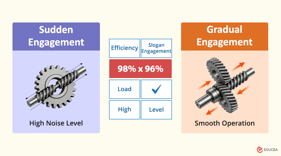
Figure 2: Performance comparison between spur gears (linear engagement) and helical gears (progressive engagement), highlighting key differences in efficiency, load capacity and noise levels for proper gear selection.
The core technical section of the paper presents a detailed comparison to lead to a critical selection between the two most common gear types. The choice between spur and helical gears involves trade-offs in operational requirements. With helical gears, the tooth mesh is again progressive, providing a basis for much smoother operation and higher load-carrying capacity. Because teeth engage one after the other, the load is spread over a greater area of contact, thereby decreasing stress and wear. However, this angular contact between the teeth involves axial thrust, which requires bearings capable of taking up this force.
In spur gears, the teeth engage simultaneously across the full face width, creating impact loading and noise; however, this design delivers higher efficiency by eliminating axial thrust. According to best practices outlined by the Society of Manufacturing Engineers (SME), helical gears are preferred for high speeds or very low noise, though they sacrifice 1-2% in efficiency.
The following are some key differences:
| Feature | Spur Gears | Helical Gears |
| Meshing Method | Linear, sudden tooth engagement | Angular, gradual tooth engagement |
| Noise & Vibration | High | Low |
| Load Capacity | Medium | High |
| Efficiency | Very High (~98-99%) | High (~96-98%) |
| Axial Thrust | None | Significant (requires thrust bearings) |
| Cost | Low | Higher |
| Ideal Applications | Low-speed, cost-sensitive systems | High-speed, high-load, quiet-operation applications |
Table 1: provides a clear overview of the fundamental differences between spur and helical gears, highlighting their distinct characteristics, performance metrics, and typical use cases.Key Factors for Industrial Gear Selection in Harsh Operating Conditions
Successful industrial gear selection requires systematic evaluation of the following factors. A checklist of decision-process considerations is provided in systematic order, focusing engineers on five critical factors.
1. Load Characteristics
First, consider the load’s nature. A constant load, as in a conveyor system, is less severe than a shock load in a crusher or press. Engineers must select gears for heavy machinery from materials and heat treatments that resist impact fatigue. Engineers often prefer helical gears for shock loading because they distribute the load more evenly.
2. Operating Speed
Speed is directly related to dynamic forces, noise, and lubrication requirements. Where low-speed applications require high torque, the design may favor strength and cost considerations; high-speed applications may require smoothness and low vibration, favoring helical over spur gears. Gear transmission efficiency also changes with speed.
3. Precision Requirements
Linked to the ASME Y14.5 standard, gear precision grades have a direct effect on transmission smoothness, noise levels, and positional accuracy. Applications that involve robotics and aerospace require high-precision gears. Manufacturers must follow strict processes to meet the required geometric tolerances and ensure optimum gear performance.
4. Operating Environment
Factors such as temperature, dust, moisture, and corrosive media dictate material selection and seal requirements. Harsh environments will call for stainless steel or specially coated gears. The selection of industrial gears should take all these conditions into account to ensure long life.
5. Spatial and Layout Constraints
The available space and required shaft orientation (parallel or intersecting) will reduce the options. Worm gears provide the most compact means of right-angle drives, and bevel gears are the only means of power transmission between shafts that intersect. Engineers must consider gear design factors such as center distance and overall envelope early in the design phase.
How Material Science and Heat Treatment Unlock Gear Durability?
Material selection and processing are integral to designing gear performance, not simply choosing a material. Materials science and heat treatment work together to achieve gear rigidity. For instance, alloy steels offer a high strength-to-weight ratio, while stainless steels provide corrosion resistance. However, all of this begins with the raw material. Heat-treatment processes like carburizing and quenching alter the material’s microstructure, creating a hard, wear-resistant surface atop a tough, fracture-resistant core. This is important for resisting surface contact stresses and preventing tooth bending fatigue.
Generally, a manufacturer with certifications such as IATF 16949 or AS9100D demonstrates tight material traceability and controls over heat treatment processes, which are crucial for ensuring gear fatigue life under heavy loads. Advanced manufacturing materials, coupled with precise heat treatments, are the keys to superior gear durability.
Can a Systematic Approach to Gear Design Prevent Costly Failures?
The case study reveals the value of a systematic selection framework in prevention and optimization. A crusher in a mining application was experiencing recurring gear failures, resulting in lengthy downtime and costly maintenance. The original design had utilized standard spur gears. By systematically applying the above framework, engineers determined that the application involved significant shock loading and required a high level of reliability. Engineers replaced the spur gears with specially designed helical gears made from carburized alloy steel. The gradual approach of the teeth in the helical gears absorbed the shock load, while the increased hardness and improved wear characteristics afforded by the new material and processing method significantly improved performance.
Service life increased 200%, accompanied by reduced energy use. This example demonstrates how customized gear manufacturing, informed by a systematic gear failure analysis, can transform performance. If you are an engineer interested in optimizing gears, the following resource provides detailed information on industrial gear types and their benefits.
Best Practices for Gear Performance at its Optimum Level
This section covers basic maintenance practices that maximize gear life and system reliability by focusing on prevention rather than correction. Proper maintenance is the decisive factor in maximizing the life of industrial gears. Key practices include choosing the right type and viscosity of lubricant to minimize wear and prevent scoring; installing and aligning to prevent uneven load distribution; and periodic condition monitoring, including vibration analysis to detect early signs of pitting or wear. Proactive maintenance practices can identify degradation before it escalates into a catastrophe, thereby avoiding unplanned downtime. Looking at the gearbox as a system, one that requires ongoing management, is the most effective strategy to reduce gear maintenance costs and ensure its long-term reliability. Conforming to Quality Control and Assurance Standards throughout the gear’s life cycle is the foundation of predictable performance.
Final Thoughts
Industrial gear selection is a multidimensional engineering decision balancing performance, cost, reliability, and application context. A systematic selection framework, supported by material science expertise and precision manufacturing, enables engineers to achieve maximum efficiency and durability in power transmission systems.
Frequently Asked Questions (FAQs)
Q1. What is the most common mistake in selecting industrial gears?
Answer: The most common mistake is focusing only on size and pitch while ignoring real operating conditions such as shock loads, misalignment, dust, and moisture. A full lifecycle assessment is essential for reliable and cost-effective performance.
Q2. When should custom gears be used instead of standard catalog parts?
Answer: Custom gears are needed when standard options cannot meet specific requirements such as space constraints, unique torque-speed profiles, ultra-quiet operation, or harsh environmental conditions. Customization allows optimized materials, heat treatment, and tooth geometry.
Q3. Is there a significant efficiency difference between spur and helical gears?
Answer: Spur gears are about 1–2% more efficient, but helical gears perform better in high-speed and high-load applications due to smoother operation, higher durability, and reduced noise.
Q4. What role do international standards like ISO play in gear manufacturing?
Answer: ISO and AGMA standards define gear geometry, accuracy, materials, and testing. Using a certified precision gear machining service ensures consistent quality, predictable performance, and reduced design risk across global supply chains.
Q5. Can proper maintenance extend the life of industrial gears?
Answer: Yes. Correct lubrication, alignment, and regular inspections, such as oil analysis and vibration monitoring, help detect issues early, prevent failures, and extend gearbox life.
About the Author
The author is a precision manufacturing expert at LS Manufacturing, a company that, since its founding, has focused on enabling engineers and researchers to overcome even the most complex component challenges in heavy machinery and automation applications. ISO 9001, IATF 16949, and AS9100D certifications ensure high-reliability custom gear solutions via advanced technologies and rigorous quality assurance.
Recommended Articles
Explore these recommended articles to discover advanced industrial gear types, precision machining techniques, and material selection strategies. Gain practical insights to optimize gear performance, extend service life, and enhance reliability in heavy machinery and automation systems.