Updated July 5, 2023

Introduction to Flowchart Symbols
A flowchart is a graphical representation of different actions and steps. It is commonly used to present the flow of algorithms, workflows, or procedures because it displays steps in a linear order. A flowchart typically illustrates the steps as different types of boxes, with arrows linking them in the proper order. Various flowchart designs are used to create various kinds of flowcharts. Each flowchart symbol has a distinct meaning and context in which it can be used. Knowing the basic symbols and what they mean will make it simpler, whether you want to read a flowchart or attempt to make one yourself. The series of actions or steps and the relationships between them are shown using lines and arrows. These are called Flowchart symbols.
List of Flowchart symbols
Here is the list of Flowchart symbols mention below
1. Branch and Control of Flow Symbols
Terminator

The Oval shape / Pill shape represents the start or endpoint of the system. It contains the “Start” or “End” word.
Process or action
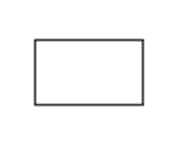
A box used to describe a single action or step or a whole sub-action within a larger process.
Decision
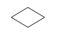
The Diamond Shape Indicates branching or decision points. From various points on the diamond, lines illustrating various decisions arise.
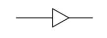
Connecting lines
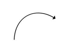
The Arrow Shape Use this symbol to link together various elements to demonstrate how the shapes relate to one another.
Yes/No Decision Point
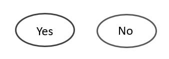
It indicates a sequence in the process where the end-user selects an answer, such as “yes-no” or “true-false,” and then branches to various sections of the flowchart.
On-Page Reference

It used to indicate connect separate processes on the same page of the process.
Off-Page Reference

It would contain a letter inside. It represents that the flow starts on another page with a matching symbol containing the same letter.
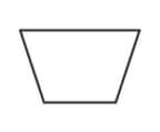
Merge Symbol

It represents multiple systems or paths that are merged into a single one.
Extract Symbol

It represents multiple systems or paths that are merged into a single one.
OR Symbol

It represents the process flow continues in more than two branches.
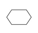
Summing Junction

It represents a point in the flowchart where several branches merge into a single process.
Control Transfer
When certain conditions are satisfied, a step proceeds to a step other than the next step.
Annotation Symbol
It represents additional information about a step in the process.
2. Process/Operation Symbols
Sub Process Symbol
A series of activities within a larger and more complex procedure, routine, or module that execute particular tasks.
Predefined Process
It demonstrates a series of steps that form a complex process described elsewhere in the drawing, usually on a different page.
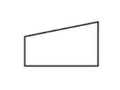
Delay

It indicates a delay in the process.
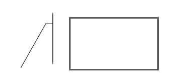
Preparation
Indicates the set-up to another step in the same process.
Manual operation
This indicates a process step that should be conducted manually instead of automatically.
Parallel Mode
It is also known as “Concurrent operation.” Two or more parallel processes or procedure phases are indicated.
3. Input and Output Symbols
Data (Input/Output)
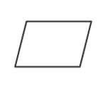
The Parallelogram Shape Indicates whether data is entering or exiting the process from the outside.
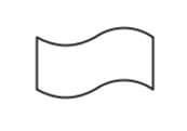
Document
This shape represents a printout, like a report or a document.
Multi-Documents

It illustrates multiple documents in the system.
Display
It represents where the information is displayed in a process.
Manual Input
This is a process step where an operator or user is asked to manually enter data.
Card
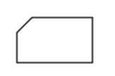
Paper Tape
It specifies the data is stored on page tapes. This symbol is also no longer frequently used.
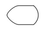
Loop Limit Symbol

It denotes the process at which a loop should stop.
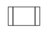
Subroutine
A set of actions that execute a particular task within a broader mechanism is denoted by this symbol.
4. Data and Information Storage Symbols
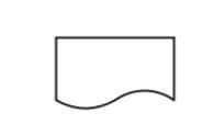
Stored Data
It is also called a data storage symbol. This specifies where data or information is stored.
Database
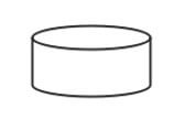
It indicates a list of information or data with a consistent structure that can be searched and sorted.
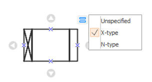
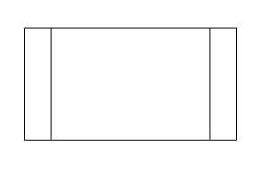
Internal Storage
this symbol denotes the information or data is stored in memory during the execution of a program.
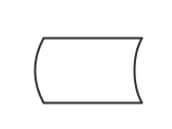
Sequential Data

Represents data that can be accessed in sequential order. The shape is meant to resemble a reel of tape.
5. Data Processing Symbols
Collate

Specifies a process step that organizes information or data into a standard format.
Sort

It indicates the arrangement of documents, data, or materials in a specific order.
Conclusion
The majority of the flowchart symbols in this article are for very particular purposes, as in a data flow diagram for computer programming. Simple flowchart symbols are used advanced for the expertise, and the diagram is being created with a group with similar knowledge. I hope you will find this article to create flowcharts.
Recommended Articles
This is a guide to Flowchart symbols. Here we discuss the Simple flowchart symbols, which are used advanced for the expertise. You may also have a look at the following articles to learn more –