Overview
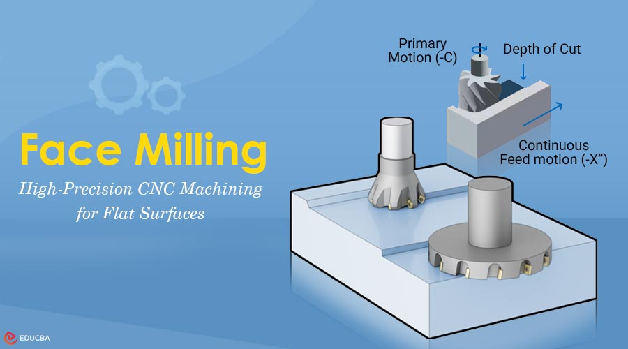
Face milling is a crucial machining process that creates flat surfaces on a workpiece using rotating face milling cutters. It is an efficient process for removing material from the face/work surface. You receive very smooth, accurate faces ready to assemble or proceed to further machining operations. This machining operation occurs faster than any other surface-finishing operation.
Compared to other surface-finishing techniques, face milling operates at a much higher rate. Modern CNC milling services commonly use face milling to manufacture components from various materials, ranging from soft aluminum to hardened steel. With various cutter sizes and designs available, understanding the basics of face milling helps in selecting the right tool for each application.
What is Face Milling?
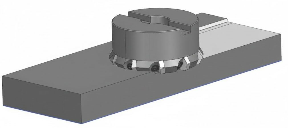
Face Milling Cutter
Face milling is a machining process used to produce flat surfaces perpendicular to the cutter’s axis of rotation. The cutter rotates, and it then moves to cut across the face of the workpiece. Multiple cutting edges remove material to cut a flat surface, making multiple passes for each cut. The diameter of the cutting tool will usually be larger than, or at least equal to, the width of the workpiece. This allows the cutter to produce complete surfaces as it quickly passes over the workpiece.
When the blade cuts through the material, the cutter engages the material’s face surface. Face milling differs from peripheral milling in that, in peripheral milling, the cutting edge does the cutting. In fact, both the face and periphery do the cutting. The cutter has a face and an edge; face milling is much faster than edge milling alone.
How Flat Surfaces are Machined?
Face Milling is a simple process for cutting flat surfaces. The face milling cutter rotates as it moves across the workpiece’s face at high speed. The material is removed progressively by making passes until it reaches the desired depth. You have to secure the workpiece to the machine table. Position the face mill over the surface at the start location.
The spindle then rotates the cutter to the desired cutting speed, and the machine engages the material. The cutter will then feed across the workpiece, removing a skinny layer of material at a time. Each cutting insert will take a chip out as it passes through. The process continues until the machine finishes the entire surface to the required dimension.
Core Difference Between Climb Milling vs Conventional Milling
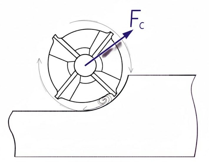
Climb Milling
Climb milling feeds the cutter with the direction of rotation. The insert will enter the cut with maximum chip thickness and exit with the thin chip. It provides a better surface finish and reduces cutting forces on the workpiece. Conventional milling feeds against the direction of rotation. The insert will enter the cut with a thin chip and build up to the maximum chip thickness.
This method is more suitable for machines with some backlash or those using older technology. Most modern CNC milling services utilize climb milling for face operations. It allows you to achieve better surface quality and increased tool life. The workpiece also suffers less stress at the cutting surface.
Depth of Cut Considerations in Face Milling for Quality and Tool Life
The depth of cut significantly affects surface finish and tool life. A shallow depth of cut will give smoother surfaces, but will take longer. Deep cuts will remove material more quickly, but sacrifice surface quality. Industry standards for the depth of cut typically range from 1mm to 3mm per pass. Softer materials, like aluminium, will not have issues with deep cut depth. Harder materials require a shallower depth of cut due to possible tool failure.
Machine rigidity will define the maximum practical depth of cut. Inadequate rigidity will generate chatter, resulting in poor quality. Always start conservative, and gradually increase your depth of cut until issues start to occur.
Face Mill Tool Design and Components
1. Cutter Bodies
Face mills are cutting tools that use indexable inserts welded to a cutter body. Inserts offer multiple cutting edges for economical efficiency. When one edge wears out, you simply index to a fresh edge. Cutter bodies range from 50mm to 400mm in diameter. Larger cutter bodies cover wider areas, but require more spindle horsepower. The size of your workpiece and your machine capacity determine which cutter diameter works best for you.
2. Inserts and Holders
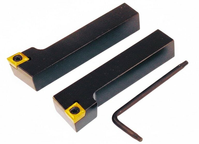
80° RH and LH Tool Holders w/Carbide Inserts
The insert geometry significantly impacts the cutting process and surface finish. Positive rake angles help reduce cutting force and make cutting easier. Negative rake angles prolong cutting edges and are resistant to interruptive cutting force.
Insert Materials and Coatings for Face Milling
1. Carbide Inserts
Carbide inserts are the best choice for all face-milling applications. A non-coated carbide insert is fine for aluminum and soft materials. A coated carbide insert offers improved life when working with steel or with challenging workpieces.
2. TiN/PVD
TiN coating offers limited wear resistance and is suitable for general-purpose machining. TiAlN coating allows cutting on harder materials at higher temperatures. PVD coating is suited for maximum performance across all material types.
3. Ceramic Inserts
Ceramic inserts are suitable for cutting hardened material at extremely high speeds. Although more expensive than other inserts, ceramic cutting tools may offer significant productivity increases if you find an appropriate use case. Ideally, match the ceramic insert to your workpiece.
Face Milling Cutter Tool Designs
1. Spindle Mounting
Face mills mount directly to the spindle or to an arbor. These work best on medium-sized surfaces with a width of up to 150mm. The compact shell mill tools make for good access into tight spaces.
2. Holders
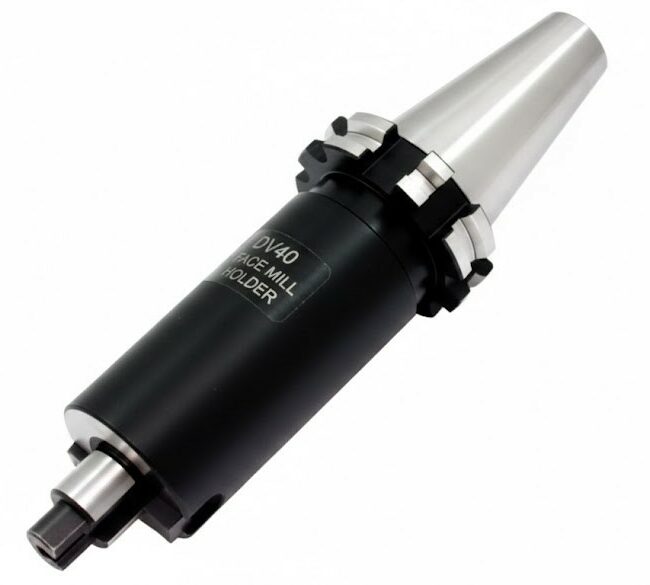
DV40 Face Mill Holder
Face mill holders precisely fit with a taper shank for a secure hold. These clamps hold larger diameter cutters securely at high speeds. Most production shops utilize this style for heavy-duty applications.
3. Modular Holders
Modular systems allow you to change insert types without buying a new cutter. You simply swap cartridges to change the cutting geometry or insert size. This type of flexibility significantly decreases your tooling inventory costs.
Key Factors Affecting Face Milling Performance and Efficiency
Cutting speed primarily determines the rate at which the cutter spins during the machining operation. Increased speeds improve productivity, but produce additional heat. The material you are cutting and the insert grade define the best cutting speed. Feed rate regulates the speed at which the cutter moves across the material’s surface.
Increased feed will decrease cycle time; however, it may affect the surface finish. You will need to weigh the feed rate against your operation’s finish requirements. Radial depth of cut refers to the distance by which the cutter extends beyond the workpiece. A larger overhang reduces the cutting forces on each insert; however, it also increases the risk of chatter. Generally, maintain a radial depth of cut between 50% to 75% of the cutter diameter.
Typical Applications of Face Milling Across Industries
Face milling services are necessary for engineered surfaces in manufacturing. Engine blocks require flat deck surfaces for correct head gasket sealing. Face milling can produce the acceptable tolerances and smooth surfaces necessary. Mould and die making utilizes face milling to create flat surfaces. The mould and die-making process can create datum surfaces with precision, enabling subsequent operations.
The process is repeatable and produces consistent results from piece to piece, enabling quick production. Structural components in aerospace and automotive also require flat surfaces. Most mounting surfaces must adhere to strict flatness tolerances. Face milling provides the reliability that many industries require.
Diagnosing Common Face Milling Issues
If the finished surface exhibits chatter marks that form a repetitive pattern, vibration is likely causing the chatter during cutting, resulting from insufficient rigidity of the cutting tool. The solution to chatter is to either reduce the depth of cut or the cutting speed. Poor surface integrity can also point to worn or damaged inserts.
First, inspect the insert for signs of wear or dullness. Also, examine the setup to ensure sufficient coolant reaches the cutting area. Dimensional Inaccuracy suggests misalignment with the machine or a thermal issue. Warm up the machine before precise work. Also, verify that the workholding is securely clamping the work without distortion.
Optimization Tips for Face Milling Operations to Improve Productivity
Always select the largest cutter diameter possible. The larger-diameter cutter disperses cutting forces across more inserts, resulting in a more even distribution. This results in a lower insert load, which equals total tool life. Use a new insert and the proper shape for the type of material. A worn insert generates more cutting force, which can lead to poor surface integrity.
Consistent indexing of the insert results in a consistent cutting shape throughout the manufacturing process. Ensure there is sufficient coolant flow into the cutting area during cutting time. Adequate cooling reduces heat buildup and increases tool life performance. Good cooling will also sometimes displace chips quickly away from the cutting area.
Best Practices for Improving Face Milling Activities and Tool Life
First, the cutting parameters are conservative, applying operational limits as a controlled investment in tooling while allowing for process observation. You will be watching for potential chatter, poor finish, or an elevated rate of wear in the tool. Simply adjust one cutting parameter to understand the others better.
Record the optimal parameters for each material and setup. This creates your library of information, saving you time on your next project. Low-cost tooling incurs additional costs in terms of time use and replacement frequency. Premium face-milling tooling delivers more repeatable results at a more predictable cost per part.
Final Thoughts
Face milling is a fundamental machining process that ensures flat, precise, and high-quality surfaces across a wide range of materials and industries. By understanding the process, cutter types, inserts, and machining parameters, manufacturers can optimize efficiency, improve surface finish, and extend tool life. Implementing best practices and monitoring key factors in face milling ensures consistent results, making it an essential operation in modern CNC machining and precision manufacturing.
Recommended Articles
We hope this comprehensive guide to face milling helps you better understand surface machining. Explore these recommended articles to gain deeper insights and improve your machining knowledge.