


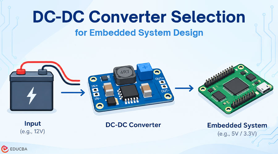
An embedded system may run from a single power source, but its components often need different supply voltages. For example, a controller powered by a 12 V supply might need regulated 5 V and 3.3 V rails for its microcontroller, sensors, and communication circuits.
Choosing a DC-DC converter involves more than matching voltages. Input fluctuations, peak current, efficiency, heat, and output noise can all affect system reliability. A proper DC-DC Converter Selection process considers these factors to identify a converter that meets the system’s electrical and performance requirements. Here’s how to evaluate those requirements and select a converter that fits your design.
Define Power Requirements for DC-DC Converter Selection
Start by documenting the input voltage range, required output voltage, and load current.
For a battery-powered device, consider how the input voltage changes as the battery discharges. For an industrial controller, account for variations in the DC supply. Use the expected minimum and maximum voltages, not just the nominal value.
Next, calculate the load current. Include both steady-state demand and short-current spikes from devices such as wireless modules.
Consider a 5 V rail supplying these components:
| Component | Maximum Current |
| Microcontroller and supporting circuits | 150 mA |
| Sensor interfaces | 200 mA |
| Communication module | 800 mA |
| Other peripherals | 100 mA |
| Total | 1,250 mA |
Adding 20% headroom gives a preliminary design target of 1.5 A.
This margin helps with component selection, but it doesn’t replace checking startup current or worst-case load conditions.
Choose the Right Topology for DC-DC Converter Selection
The input and output voltage requirements determine which converter topology makes sense.
| Topology | Example | Typical Use |
| Buck | 12 V to 5 V | Stepping down a supply voltage |
| Boost | 3.7 V to 5 V | Raising battery voltage |
| Non-inverting buck-boost | 9–18 V to 12 V | Regulating across a changing input |
| Isolated DC-DC | 24 V to isolated 5 V | Separating electrical domains |
A buck converter works when the input stays sufficiently above the required output. A boost converter raises a lower input voltage. If the input can move above and below the target voltage, a non-inverting buck-boost converter may be a better choice.
Check the specific topology before selecting a part. Some basic buck-boost circuits produce a negative output rather than the positive voltage your system needs.
Decide Whether Electrical Isolation Is Needed
DC-DC converters are also classified as isolated or non-isolated.
An isolated converter provides a galvanic barrier between its input and output circuits. A non-isolated converter typically shares a common ground between the two.
For many embedded boards, a non-isolated design is practical. It generally requires fewer components and can offer a smaller footprint and high efficiency. Including isolation requirements early in the DC-DC Converter Selection process helps narrow down suitable options.
When comparing power architectures, understanding the advantages and limitations of non-isolated DC-DC converters can help you decide whether a shared-ground design is appropriate.
Isolation may be necessary when circuits operate at different ground potentials or when electrical safety requirements call for a defined isolation barrier. Make that decision before comparing size, efficiency, or cost.
Compare Efficiency and Thermal Performance
Higher efficiency means less input power is wasted during conversion, reducing the heat the power supply must dissipate. Therefore, efficiency should remain an important consideration during DC-DC Converter Selection, particularly in compact embedded systems.
Suppose a converter delivers 5 V at 1.5 A:
Output power = 5 V × 1.5 A = 7.5 W
At 90% efficiency, the converter draws approximately 8.33 W and loses 0.83 W.
At 95% efficiency, input power drops to approximately 7.89 W, with only 0.39 W lost.
That’s roughly 0.44 W less heat generated across the power-conversion circuit. The efficiency figures here are illustrative, not measured results for a particular device.
Actual efficiency varies with input voltage, output current, and operating conditions. Review the manufacturer’s efficiency curves rather than relying on a single headline figure.
Thermal design matters as much. PCB copper area, airflow, enclosure temperature, and nearby heat sources all influence operating temperature. A converter rated for 3 A may not deliver that current continuously under every thermal condition.
Practical Example of DC-DC Converter Selection for a 12 V Controller
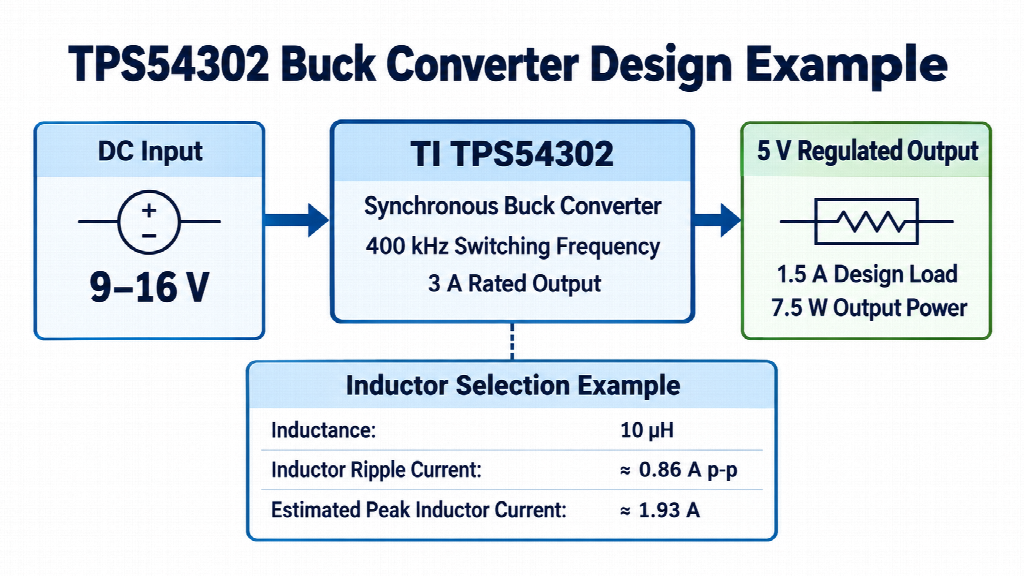
Consider an embedded controller with these requirements:
- Input voltage: 9–16 V
- Output voltage: 5 V
- Maximum design load: 1.5 A
- Required output power: 7.5 W
Because the input remains above 5 V, a synchronous buck converter is a suitable starting point.
One candidate is the Texas Instruments TPS54302, a 3 A synchronous buck regulator with a recommended input range of 4.5–28 V and a fixed 400 kHz switching frequency.
Its input range covers the required supply, and its 3 A output rating provides margin above the 1.5 A design load.
Check the Inductor Current
The inductor must handle both the average output current and the ripple current generated during switching.
Using a 10 µH inductor, a 16 V input, a 5 V output, and a 400 kHz switching frequency, the approximate peak-to-peak inductor ripple current is:

At a 1.5 A load, the estimated peak inductor current becomes:

The selected inductor needs adequate saturation and RMS current ratings, with allowance for temperature and component tolerances. Also check the regulator’s current-limit specifications.
These calculations provide a starting point, not a complete component design. Follow the manufacturer’s recommended circuit and verify that the external components meet the required operating conditions.
Check Output Ripple and Load Response
Output voltage quality matters, especially when the supply powers sensitive sensors or communication circuits.
Review the datasheet’s output capacitor recommendations, ripple performance, and load-transient behavior. Ceramic capacitor values can decrease under DC bias, so their effective capacitance may be lower than the nominal rating.
During prototype testing, measure output ripple and observe how quickly the voltage recovers when the load changes, such as from 0.5 A to 1.5 A.
Evaluate the converter at both ends of its input voltage range and under anticipated operating temperatures. A regulator that meets its nominal specifications on paper still needs to work on the finished PCB.
Check the Datasheet and PCB Requirements
Before approving a converter, review its recommended operating conditions and absolute maximum ratings. These specifications are essential during DC-DC Converter Selection, as absolute maximum ratings represent stress limits rather than normal operating targets.
Pay particular attention to:
- Voltage and current limits: Confirm the full input range and expected load conditions.
- Protection features: Check overcurrent, overvoltage, undervoltage, and thermal protection behavior.
- External components: Follow the manufacturer’s recommendations for inductors and capacitors.
- Package and layout: Verify the footprint, thermal requirements, and PCB routing guidance.
Switching regulators are sensitive to layout. Keep high-frequency current loops compact, place input bypass capacitors close to the regulator, and route feedback traces away from noisy switching nodes.
Even a suitable IC can perform poorly if its PCB layout introduces excessive noise or interferes with regulation.
Verify Component Availability and Alternatives
Electrical performance isn’t the only consideration when moving toward production. Component availability, traceability, and replacement options also matter.
Record the complete manufacturer part number in your bill of materials (BOM), along with the approved package and electrical specifications.
When researching sourcing options, VigorComp can also help you find electronic components and review available part listings.
Any replacement still needs engineering approval. Matching the output voltage or current rating alone doesn’t make two converters interchangeable. Check the pinout, input limits, switching behavior, protection features, thermal performance, and external component requirements.
Validate the Final Design
Once you’ve narrowed down the options, test the converter under realistic operating conditions.
Check startup behavior, voltage regulation, output ripple, and temperature rise across the expected input and load ranges. Include rapid load changes and any environmental conditions the finished product will encounter.
Document the test results alongside the approved datasheet and BOM. This gives engineering and purchasing a clear reference if the design needs revision or a component becomes unavailable.
Final Thoughts
Effective DC-DC Converter Selection starts with a clear understanding of the system’s power requirements. From there, the right topology, current capability, efficiency, and thermal performance help narrow the options.
Datasheet specifications and calculations can identify promising devices, but prototype testing determines whether they meet the finished system’s needs. A disciplined selection process helps avoid power-related failures and makes the design easier to manufacture and maintain.
Recommended Articles
Discover how DC-DC Converter Selection helps engineers design reliable embedded systems with efficient power conversion. Explore our recommended articles on DC-DC converter types, power supply design, voltage regulation, switching regulators, and embedded system power management.